
I2C Multiplexer ESP32 OLEDs
Did you know you can easily connect multiple displays or sensors to just one microcontroller? Welcome back to MaisonUp! Today, we introduce you to a powerful tool—the I2C Multiplexer.
When working with microcontrollers, efficient wiring is key, especially for complex projects. That’s where I2C (Inter-Integrated Circuit) comes in! Unlike SPI (Serial Peripheral Interface), which requires multiple wires per device, I2C simplifies connections to just two:
🔹 SDA (Data)
🔹 SCL (Clock)
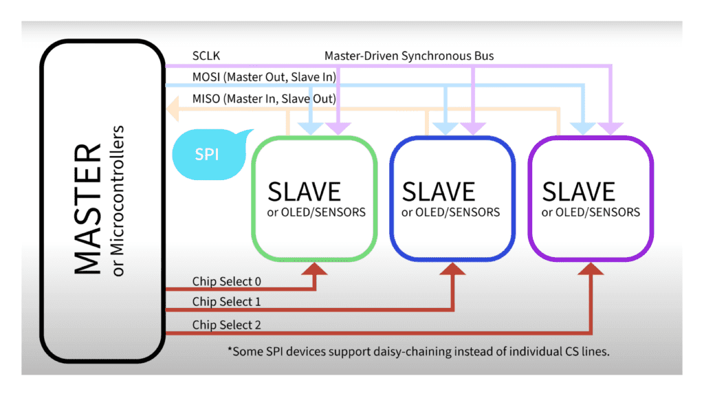

For example, take these two OLED displays:
The left one uses SPI and requires six connections.
The right one uses I2C, needing only four connections.
With I2C, you can connect multiple devices using the same two lines, making it perfect for compact and scalable projects.

Address Conflicts in I2C & the Solution
I2C works smoothly when devices have unique addresses. But what if two devices share the same I2C address?
This creates a conflict—since I2C requires unique addresses, the microcontroller can’t differentiate between the devices, making them unusable on the same bus.
That’s exactly where the I2C Multiplexer comes in!
The PCA9548A Multiplexer allows you to connect up to eight I2C devices, even if they have the same address. How? It switches between devices in software, letting your microcontroller communicate with one device at a time.

Let’s Build It!
To demonstrate how this works, we’ll use:
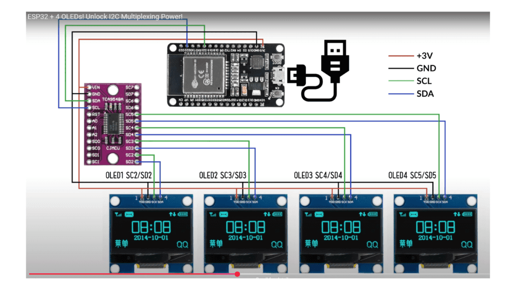
Wiring Diagram
ESP32 + I2C Multiplexer + 4 OLEDs
Follow this wiring setup carefully:
- ESP32 to TCA9548A:
- SDA → SDA
- SCL → SCL
- VCC → 3.3V
- GND → GND
- Multiplexer to OLEDs:
- Each OLED is connected to a different channel (SCx/SDx)
Setting Up the Software (No Experience? No Problem!)
Here’s how to set it up in Arduino IDE step by step.
Step 1: Install the ESP32 Board in Arduino IDE
Open Arduino IDE (make sure it’s updated).
Click on Boards Manager in the left panel.
Search for ESP32 and install ESP32 by Espressif (this might take some time).
Once installed, you’ll see a confirmation message at the bottom of the screen.
Step 2: Install the Required Libraries
Adafruit_SH110X – Required for 1.3-inch OLED displays
Wire – Ensures smooth I2C communication
Important: If you’re using smaller 0.96-inch OLEDs, you’ll need Adafruit_SSD1306 instead of Adafruit_SH110X.
Go to Library Manager (left panel).
Search for Adafruit_SH110X and install it.
Ensure the Wire library is installed as well.
Step 3: Load the Code & Configure Settings
Open the following code in Arduino IDE
Before uploading, let’s set the correct configurations:
Go to Tools > Board and select the correct ESP32 version (e.g., WROOM).
Select the correct COM port (under Tools > Port).
Verify the I2C address of your OLED display (most are 0x3C).
					// Demo code to run multiple OLED displays with one ESP32 microcontroller
// Using I2C multiplexer PCA9548A to control up to 4 OLEDs
// Allows users to enable/disable specific OLEDs as needed
// @Copyright @MaisonUp

// Include necessary libraries for OLED display
#include <Wire.h>
#include <Adafruit_GFX.h>
#include <Adafruit_SH110X.h>

// Define OLED display size
#define SCREEN_WIDTH 128
#define SCREEN_HEIGHT 64
#define OLED_RESET -1  // Reset pin (not used for SH1106)

// WiFi Credentials (Reserved for expansion, not needed for this demo)
const char* ssid = "XXXXXX";
const char* password = "XXXXXXX";

// Create display object
Adafruit_SH1106G display(SCREEN_WIDTH, SCREEN_HEIGHT, &Wire, OLED_RESET);

// PCA9548A I2C Multiplexer address
#define PCA9548A_ADDR 0x70

// Define OLED channels used in Multiplexer (Change as per your connections)
#define OLED1_CHANNEL 2
#define OLED2_CHANNEL 3
#define OLED3_CHANNEL 4  // Uncomment below if using only 2 OLEDs
#define OLED4_CHANNEL 5

#define WHITE 1  // Define WHITE color manually

// Function to select the correct OLED channel on the I2C multiplexer
void selectMuxChannel(uint8_t channel) {
    Wire.beginTransmission(PCA9548A_ADDR);
    Wire.write(1 << channel);
    Wire.endTransmission();
    delay(10); // Small delay for stability
}

void setup() {
    Serial.begin(115200);
    Serial.println("Starting ESP32 Multi-OLED Demo");

    Wire.begin(21, 22); // Initialize I2C communication with ESP32 default pins

    // Initialize each OLED separately
    for (int i = 0; i < 4; i++) { // Adjust loop if using fewer displays
        selectMuxChannel(i);
        if (!display.begin(0x3C)) {
            Serial.print("OLED ");
            Serial.print(i + 1);
            Serial.println(" init failed!");
        } else {
            Serial.print("OLED ");
            Serial.print(i + 1);
            Serial.println(" initialized!");
        }
        display.clearDisplay();
        display.display();
    }
}

// Function to display content on OLED1
void displayOLED1() {
    selectMuxChannel(OLED1_CHANNEL);
    display.clearDisplay();
    display.setTextSize(3);
    display.setTextColor(WHITE);
    display.setCursor(10, 2);
    display.print("OLED 1");

    // Animated graph effect at the bottom
    int yBase = 55;
    for (int x = 0; x < SCREEN_WIDTH; x += 8) {
        int height = random(5, 15);
        display.drawLine(x, yBase, x, yBase - height, WHITE);
    }

    display.display();
}

// Function to display content on OLED2
void displayOLED2() {
    selectMuxChannel(OLED2_CHANNEL);
    display.clearDisplay();
    display.setTextSize(3);
    display.setTextColor(WHITE);
    display.setCursor(10, 2);
    display.print("OLED 2");

    // Animated graph effect at the bottom
    int yBase = 55;
    for (int x = 0; x < SCREEN_WIDTH; x += 8) {
        int height = random(5, 15);
        display.drawLine(x, yBase, x, yBase - height, WHITE);
    }

    display.display();
}

// Function to display content on OLED3
void displayOLED3() {
    selectMuxChannel(OLED3_CHANNEL);
    display.clearDisplay();
    display.setTextSize(3);
    display.setTextColor(WHITE);
    display.setCursor(10, 2);
    display.print("OLED 3");

    // Animated graph effect at the bottom
    int yBase = 55;
    for (int x = 0; x < SCREEN_WIDTH; x += 8) {
        int height = random(5, 15);
        display.drawLine(x, yBase, x, yBase - height, WHITE);
    }

    display.display();
}

// Function to display content on OLED4
void displayOLED4() {
    selectMuxChannel(OLED4_CHANNEL);
    display.clearDisplay();
    display.setTextSize(3);
    display.setTextColor(WHITE);
    display.setCursor(10, 2);
    display.print("OLED 4");

    // Animated graph effect at the bottom
    int yBase = 55;
    for (int x = 0; x < SCREEN_WIDTH; x += 8) {
        int height = random(5, 15);
        display.drawLine(x, yBase, x, yBase - height, WHITE);
    }

    display.display();
}

void loop() {
    displayOLED1();
    displayOLED2();
    displayOLED3();
    displayOLED4();
}
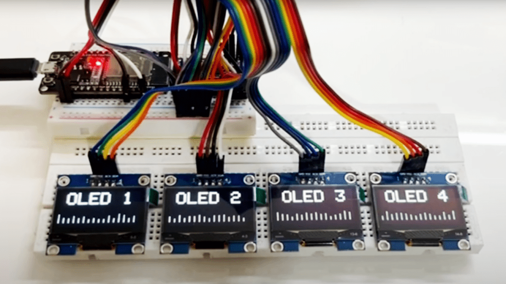
Final Output
Once the code is uploaded, you will see each OLED displaying different information sequentially!
Troubleshooting Tips
OLEDs not displaying correctly?
Double-check I2C addresses (0x3C or 0x3D).
Ensure you installed the correct libraries (Adafruit_SH110X for 1.3″ OLEDs).
Try adding pull-up resistors if I2C communication is unstable.
Conclusion
With this setup, you can expand your ESP32 to handle multiple I2C devices without conflicts. Whether you’re building a dashboard, a robot display, or an IoT project, this method will make your project more scalable and organized.
Have questions? Drop them in the comments!
Watch the full tutorial below
Stay tuned for more DIY electronics projects from MaisonUp and watch complete Project Tutorial below!